General information
Advanced communications technology, as well as measuring and control systems call for perfect signal transmission. In order to eliminate any risk of personal injury and damage to or even destruction of installations as a consequence of overvoltage conditions, these influences must be limited to harmless levels by means of overvoltage arrestors. Overvoltage conditions are distinguished in terms of internal and external overvoltages.
Internal overvoltage conditions occur because of switching of inductive circuits, spark-over, conductive coupling with higher voltage potentials and influences of other components.
External overvoltage conditions impact the system through connecting lines; in the form of inductive coupling caused, for instance, by fields of a power supply line or switching process; in the form of capacitive coupling caused, for instance, by atmospheric fields.
Operation
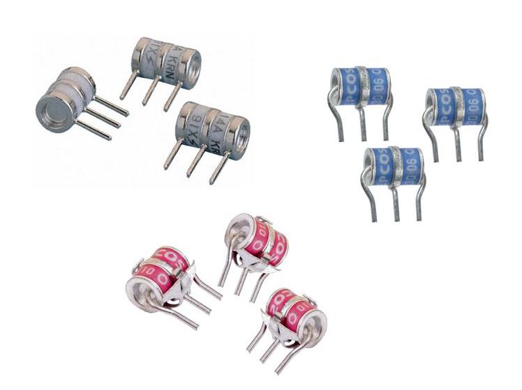
The operation of overvoltage arrestors (gas discharge tubes, GDTs) is based upon highly efficient gas discharge principles. In electrical terms, a GDT behaves like a voltage-controlled switch (Figure 1). As soon as the overvoltage exceeds the GDT's sparkover voltage, a defined discharge occurs in the component. The hermetically sealed GDT's electrical specifications are highly dependent upon certain parameters, such as gas type, gas pressure and spark gap. The discharging process destroys the energy within a short time. With its high current carrying capacity, the arc thus generated prevents, at more or less constantly low arc voltage (approximately 20 to 40V), a further build-up of the overvoltage. After the influence has decayed, the arc in the GDT is interrupted (arc extinction) and the internal resistance of the component immediately rises to a value of >1000MΩ.
In practical application, the GDT is connected in parallel with the information transmission system to be protected (Figure 2). Its internal resistance is extremely high at operating voltage and falls to nearly <0.1Ω when an overvoltage condition occurs, thereby shorting the operating voltage and the overvoltage. In common telecommunication circuits and/or systems with an operating voltage of less than 60 VDC, the GDT's arc extinction is ensured after elimination of the influence. In the case of systems with an operating voltage of more than 60 VDC or with lower impedance, the GDT's extinction behavior must be checked case by case.
If, for instance, GDTs are used in conjunction with power or voltage supply systems (e.g. main sockets), precise examination of the extinction behavior is mandatory.
Optimally, the GDT meets the requirements of a protection element: the overvoltage is safely limited to permissible levels, and due to its high insulation resistance and very low self-capacitance (<5 pF) under undisturbed conditions, the GDT has virtually no influence on the protected system.
In addition to the parameters mentioned above, the degree of primary ionization of the enclosed gas volume plays a crucial role in considering the rise time of the GDT during initial firing. Without primary ionization of the gas volume, the initial ignition in the GDT (dark discharge effect) is delayed. The use of additional ionization sources (subject to special specification) reduces the ignition level during initial ignition.
The response behavior of the GDT is greatly influenced by the rate of rise of the interference influence. The response time of the GDT is generally defined in the 0,1 μs range, with the previously mentioned rate of rise of the overvoltage playing the most important part in which context the response voltage ranges for “static“ and “dynamic interference influences“ are distinguished (Figure 3).
In the case of a dynamic influence (steeper voltage waves) the GDT's firing voltage is above the response DC voltage (VSi > VcdcN) that is due to the finite ionization time of the gas.
Push-pull interferences due to non-synchronous ignition of the discharging distance (against earth) are avoided by three electrode arrestors. A common discharging space ensures almost simultaneous ignition events at different interference levels.
GDTs are exclusively designed for transient loads (see ITU recommendation K12).
A GDT exposed to permanent loads (e.g. under power crossing conditions [influence due to contact of the system to be protected with power and voltage supply systems), will be destroyed by overheating. Three electrode arrestors with external temperature protection (fail-safe) can be used to prevent damage to installations and overvoltage protection equipment as a consequence of over temperature of the GDT. In such a case, an external short-circuit bridge shorts the overheated GDT against earth.
Features and benefits
- Standard overvoltage protection elements
- Reliable technology
- Limit overvoltages
- Absorption of high currents
- Low capacitance
- VDSL2/G.FAST compliant
- Two and three electrode versions
- Thermal overload protection
- Meets international standards


